Brushless DC machine model
Model assumptions
- Linear iron magnetization with no saturation
- Constant self and mutual inductance
- Uniform air-gap
- No slot harmonics
- Winding arrangement that produces a perfectly trapezoidal back-EMF waveform (at constant speed)
- No zero phase sequence (system is balanced)
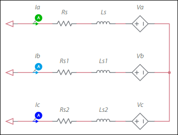
Configuration of the machine electrical system
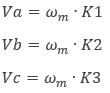
where
ωm = mechanical angular speed
K1, K2, K3 = speed factors (see figure below)
The figure below illustrates speed factor vs. angle waveforms:
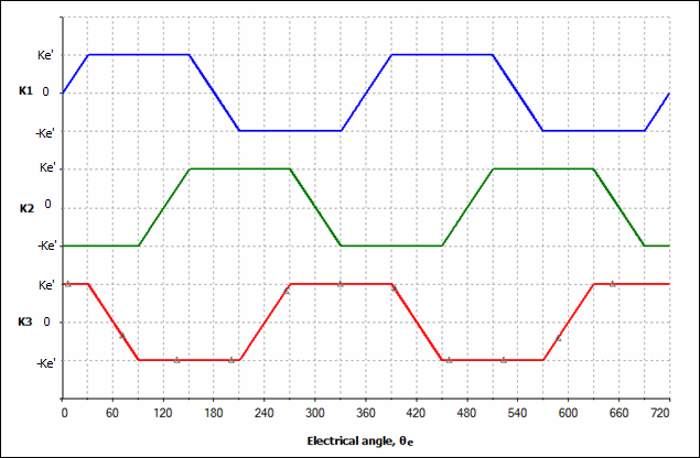
θe = θm * P
where
θe = electrical angle
θm = mechanical angle
P = number of rotor pole pairs
The generated electromagnetic torque, Te, is:
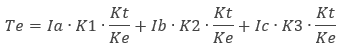
Kt = torque constant
Ke = speed constant
This component contains the following properties in the Model section of the right pane:
| Variable | Description |
|---|---|
| Stator inductance | Inductance of the stationary portion of the motor. |
| Stator resistance | Resistance of the stationary portion of the motor. |
| Speed constant | The plateau value of the trapezoidal waveform in the diagram above is Ke′=Ke/2 |
| Torque constant | Typically equal in value to the speed constant. (Kt in the generated electromagnetic torque equation in Configuration of the Machine Electrical System above.) |
| Number of pole pairs | Number of rotor pole pairs. |
| Shaft inertia | Inertia of the shaft in kg•m<sup>2</sup>. This is J<sub>rotor</sub> on the machine model diagram in <a href="/help/components/machine-modeling/">Machine modeling</a>. |
| Shaft friction | This is F<sub>rotor</sub> on the machine model diagram in <a href="/help/components/machine-modeling/">Machine modeling</a>. |
| Initial angular speed | Rotational measurement of the shaft angle in rad/s at the start of the simulation. |
| Initial angle | Initial shaft angle in radians. |